
By Mike Darwin
External Cooling Using the Portable Ice Bath (PIB)
 The first generation PIBs consisted of a waterproof vinyl tank which snapped to a rigid frame of 1-1/4″ OD PVC plastic pipe. The PIB could be partially broken down for transport to the patient’s location. However, these first generation PIBs were bulky, extremely fragile, impossible to move rapidly via commercial air freight, and could not be used in small aircraft such as are used by air ambulance services.

Figure 23: At left, a rugged PIB constructed from square aluminum tube stock with roller base; A) head ice positioner (HIP), B) single piece seamless puncture resistant vinyl liner, C) cold water supply line to HIP and water diffusers for the patient’s body, D) cooling blanket for chilling the dorsal surface of the patient, E) cold water diffusers, F) cold water supply line to diffusers, G) splash abating diffuser on drain line, H) pump and valve assembly (AC), I) drain line.
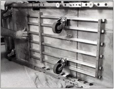
Early in 1995, the PIB was redesigned so that it would be collapsible, easily air transportable and extremely rugged. Since that time there have been many designs for PIBs executed around the world. The PIB design shown here can be assembled by one person in approximately 10 minutes. The lightweight aluminum construction means that it can be easily transported in a standard automobile trunk or as passenger luggage by air (both before and after patient use). This PIB was also designed to be small enough and easy enough to break down and re-deploy, so that it can be used in commercial air ambulances for air transport of patients while cardiopulmonary support or other interventions requiring access to the patient are underway.
Assembling the PIB
The PIB may be assembled using the following procedure:
NOTE: A step-by-step photographic summary of the PIB assembly procedure is presented in A Visual Guide to Assembly of the PIB immediately following the written description of the procedure.
1) Unfold the Roller Base and lay out the components of the PIB in an organized fashion to make sure all parts are present:
Quantity Item
1 Folding Frame
1 Roller Base
1 Vinyl Liner
2 IV Pole
8 Locking Pins
4 Attaching (Cotter) Pin assembly for securing Roller Base to Folding Frame
1 Cotter Pin for securing the Locking Bars on the underside of the Folding Frame
1 Privacy Cover
1 Records & Supplies Holster (at foot)
1 Portable Oxygen Pack Holder (POP) (and Medications Tray)
2 Heavy duty plastic tarpaulins
2) Unfold the Folding Frame into its fully deployed configuration and insert the 8 Locking Pins (with rings on the top) into the four holes on each side of the center portion (top and bottom) of the middle section of the Folding Frame.
3) Open the Roller Base and slide the locking bars on the underside of the Roller Base Plate into position. Secure the locking bars with the Cotter Pin.
4) Orient the Roller Base to the Folding Frame properly. The top surface of the Roller Base and the inside of the Folding Frame are labeled “Head” and “Foot” with matching, brightly colored tape.
5) Tilt the Roller Base so that it will fit inside the Folding Frame and the square aluminum channel on the bottom of the Folding Frame lines up with the square tubing stock of the Roller Base Plate.
6) Push the channel on the Folding Frame up onto the bar-stock of the Roller Base.
7) Insert the Attaching Pins into the holes on the bottom of the Roller Base.
8) Position the Thumper Board of the MII-HLR in the correct position on the top end surface of the Roller Base.
9) Correctly align the Vinyl Liner with the Folding Frame and secure it to the Folding Frame by mating the male and female Velcro.
10) Insert the IV Pole into the hole in the aluminum tubing of the Folding Frame in the position most convenient as dictated by the needs of the patient (location of the IV site, position of personnel, etc.).
11) Attach the Records and Supplies Holsters to the head end of the Folding Frame.
12) Place the Portable Oxygen Pack (POP) Holder over the lower 1/4th of the top of the PIB and rest the POP on it.
 Figure 24: An essential accessory to the PIB is a combination E oxygen cylinder carrier and medications/instrument tray. Early in CPS the tray may be used to hold Transport medications. Once the medications have been administered the tray can be flipped over to allow racking and safe transport of the high pressure oxygen cylinders driving the heart-lung resuscitator (HLR).
A Visual Guide to Assembly of the PIB
 A: Components of the Portable Ice Bath (PIB) prior to assembly.
 B: Accessory Bag containing Locking and Attaching Pins, Allen wrenches and spare parts.

C: The Folding Frame in the collapsed configuration.

D: Open the Folding Frame by pulling apart the two endplates.
 E: Fully expand the Folding Frame and make it rigid by inserting the eight locking pins.
F: Rigidify the Roller Base by sliding the Locking Bars across the hinge of the Roller Base.
 G: Secure the Locking Bars in position by placing the Cotter Pin into the securing bracket

H. Insert the Roller base into the Folding Frame and snap the metal channel of the Roller Base onto the metal tubing of the Folding Frame.

I: Secure the Folding Frame to the Roller Base with the four Attaching Cotter Pins. Be sure to have the locking end of the Cotter Pin point to the inside of the Roller Base.

J: It is critically important that the eight Locking Pins be inserted into the Folding Frame both at the top and the bottom of the center section of the Folding Frame. Be sure to double check for proper placement of all pins prior to covering the Folding Frame with the Vinyl Liner.

K: The Roller Base with the Folding Frame Attached should look like this after assembly.

L: Place the Thumper Board onto the Roller Base being sure to anchor it into position using the Velcro on the Thumper Board and Roller Base.
M: Unfold the Vinyl Liner inside the Folding Frame on the Roller Base.

N: Anchor the top of the Vinyl Liner to the Folding Frame using the Velcro on the lip of the Liner and the top of the square tubing of the Folding Frame.
 O: Insert the IV Pole into any of the four positions on the Folding Frame as convenience dictates.
 P: The fully assembled PIB shown without the POP/Medications Tray or the Records and Supplies Holster.
Initiating External Cooling with the PIB
Preparation of the PIB for Use
 Figure 25: The PIB in use during a patient transport from a hospital in Northern California.
Upon arriving at the site where Transport is to take place the PIB should be assembled per the instructions above and, if time permits, the liner should be carefully inspected for punctures. A repair kit is included with the liner and will affect water tight repairs in ~30 minutes.
If transport is to be undertaken in a home, or in a room where there is carpeting, the heavy duty tarpaulins should be used to cover the carpeting in the work area. Use duct tape to secure the tarps to the carpeting to avoid creation of a trip hazard from folds that will develop in the tarps if they are left unsecured.
Once a place to store the PIB has been secured until the patient is pronounced the PIB should be fully outfitted with all ancillary equipment needed for induction of hypothermia, as well as with all equipment and supplies that will be immediately required to facilitate stabilization of the patient.
The dorsal cooling blanket should be positioned in the bottom of the PIB and connected to the pump that supplies cold water to the surface convective cooling device (SCCD) as well as to the cooling blanket.
If space is constrained, as it usually is in a hospital or extended care facility (ECF), ancillary equipment and supplies may be stored inside the PIB and the entire assembly covered with a sheet to avoid attracting attention, reduce the risk of pilferage of equipment and supplies, and protect the PIB and its contents from dust and fluids as shown in Figure 26.
 Figure 26: At left, the PIB set-up for Transport in hospital with ancillary equipment in position. At right the PIB adjacent to ice in coolers, the medications kit (light green box) and other required supplies. The PIB is covered with a Nylon sheet to protect its contents and avoid attracting attention.
As soon as legal death is pronounced, remove all clothing from the patient such as hospital gowns, undergarments, and anti-embolism stockings. The most expedient and practical way to remove clothing is to cut it off using bandage scissors or the Super Scissors contained in the RSK. The patient’s genitals must remain covered at all times during transport and external cooling. The genitals may be covered with a towel or small disposable drape sheet. This is an important gesture of respect and is not just a courtesy to the patient and personnel who may come in contact with the patient; it is also the law in many states. Failure to offer this respect can result in civil prosecution.
The combination fecal retention device (FRD), thermocouple probe, and colonic lavage tube should be inserted into the rectum and inflated with 30 mL of air. Easy passage of the FRD should be facilitated by lubricating it with surgical jelly before insertion (do not use oil based lubricants, including silicone lubricants, as they will destroy the retention balloon). The FRD will allow for immediate determination of the patient’s temperature, either at the time of pronouncement, or whenever Transport is permitted to begin. The FRD may also be used to irrigate the colon with cold electrolyte balanced physiologic solution (do not use water!). This will render further rectal temperature readings inaccurate, but the tradeoff in terms of speeding cooling is well worth it. Step by step instructions for insertion of the FRD and colonic irrigation are given in Colonic Lavage Cooling, below.
As soon as possible after legal death is pronounced, the patient should be rapidly transferred to the PIB and the HLR applied (manual CPR should only be used as a bridge between the time legal death is pronounced and the time it takes to organize transfer of the patient into the PIB if transfer to the PIB cannot be carried out immediately). Once the patient is positioned in the PIB and mechanical CPR has been started, the patient should be packed in ice from head to foot. The PIB, which uses crushed ice in direct contact with the patient’s skin, will more than double the rate of cooling that can be achieved with ice-filled plastic bags. The PIB is many times more effective at reducing patient core temperature than simple air cooling such as is achieved by placing the patient in a refrigerated morgue or “reefer” unit.
 Figure 27: 300 mL Vindicator quaternary ammonium disinfectant should be added to the heat exchange water in the PIB to kill the most common transmissible human pathogens.
Concurrent with the addition of ice to the PIB, 5 gallons of water containing 300 ml of Vindicator Disinfectant (10% didecyl dimethyl ammonium chloride and 6.76% n-alkyl [C14 50%, C12 40%, C16 10%] dimethyl benzyl ammonium chloride) should be added to the PIB as a microbicide.[158] The combination of quaternary ammonium compounds present in Vindicator is effective at killing the pathogens listed in in the box below. Because of the low temperature in the PIB, microbial kill times will be longer, and it may take as long as 5 minutes after disinfectant is added until the microbial burden in the PIB water is reduced or eliminated. Quaternary ammonium compounds have very low toxicity and are generally not irritating to the oral mucosa or the conjunctiva. Used in the proper concentrations these compounds are safe for use with disposable stainless steel heat exchangers, such as those incorporated into combination hollow fiber oxygenator-heat exchanger devices used in cardiopulmonary bypass. Quaternary ammonium compounds should not be used with aluminum blood heat exchangers.
|
CAUTION: Do not place ice in the PIB before the patient is transferred into it, as the presence of ice (particularly if an MII-HLR is being used) will make proper application of the HLR impossible. Exercise care to avoid wetting the piston of MII-HLR units as it will cause the piston to “lock-up” and the unit to stop cycling!
 Figure 28: The Fecal Retention Device (FRD) consists of a rigid, fenestrated tube with a tough silicone rubber balloon near the tip. The FRD is outfitted with a Cu++/C thermocouple probe to allow for immediate determination of the patient’s core temperature at the time Transport begins. The silastic balloon is inflated with 50 mL of air to hold the FRD in place and prevent leakage of feces into the refrigerating water of the PIB. The FRD tube is covered with a caplug, but this may be removed and the tube connected to a closed cold physiologic solution irrigation set-up to facilitate more rapid induction of hypothermia.
The Surface Convection Cooling Device (SCCD)

Figure 29: Current implementation of the Surface Convective Cooling Device (SCCD). For use where there is no AC power, or in situations where the patient will have to be immediately relocated following the start of CPS, an Atwood self-contained battery operated marine bilge pump should be used. The SCCD above uses 4 circular diffusers to distribute cold water over the patient’s body and a Head Ice Positioner (HIP) to hold ice around the patient’s head. The HIP is also supplied with cold water from the SCCD pump and has a diffuser which may be placed on the patient’s forehead to deliver chilled water to cool the forebrain.
One of the principal barriers to efficient external cooling is the existence of “boundary layers” of insulating water which become established around the patient in the PIB. Anyone who has ever been on a camping trip and had the frustrating experience of trying to melt snow for drinking water will immediately understand this phenomenon. In the center of the kettle will be a mass of snow surrounded by tepid water while the water near the wall of the pot is boiling. Only by stirring can such boundary layers be disrupted and efficient heat exchange achieved. One solution to this boundary-layer problem was the development by Fred Chamberlain, and consisted of a circulating pump and ice water distribution assembly that can be used in the PIB.[156]
This device, known as the Surface Convective Cooling Device (SCCD), exists in a variety of implementations. It’s most basic implementation consists of a 40 GPM (gallons per minute) output, lightweight, mains powered (AC) submersible sump pump, which is connected to a manifold of hoses and small sprinkler heads (Figure 33 ). The hosing and sprinkler heads – using quick disconnects – snap rapidly into any desired configuration. Sprinkler heads may be positioned so that a fast moving stream of ice cold water can be directed over the patient’s head, as well as to other key heat exchange areas, such as the axilla and groin. Alternative designs which employ a rigid tubing manifold with slotted cooling “fingers” have also been developed. However they operate, the principle remains the same: to rapidly move large adequate volumes of chilled water over the surface of the patient.
 Figure 30: Close up of one of the four cold water diffuser rings used in the SCCD.
Three shortcomings of these SCCD designs is that they do not uniformly sheet or film water over the surface of the patient’s body, they do not reliably apply stirred cold water to the patient’s head, and finally, they generate splashes and aerosols that may transmit infectious disease. This has become a particular concern with the advent of multi-resistant Staphylococcus aureus (MRSA).[159], [160] Most in-hospital Staph infections are now MRSA and other, even more dangerous strains of antibiotic resistant organisms are on the way.[161]
A solution to these problems has come in the form of a more efficient SCCD which is more easily and rapidly applied. It consists of modified diffusers consisting of 4 rugged plastic rings with perforations positioned and immobilized inside two wire-reinforced fabric frames. The side of the frame that is placed facing the surface of the patient is made of an open-mesh nylon fabric that allows the free flow of water (Figures 31-32 ). The opposite side of the fabric frame is comprised of a solid fabric panel to reduce the risk of water spraying or splashing from the PIB onto staff caring for the patient.
 Figure 31: Above, A) cross-linked Dacron polyester wool blanket, B) Cold water delivery control valve for the HIP, C) insulating plastic covered foam mattress, D) HLR backboard.
These two frames holding the cold water diffusers are then placed atop a blanket consisting 2” thick cross-linked Dacron polyester wool which serves as a spreading medium for the cold water over the patient’s body (Figure 32). The entire assembly is then covered with a very thin sheet of nylon tricot or Dacron polyester fabric.
 Figure 32: Cutaway looking “up” from the surface of the patient showing the relationship between the fabric frame, cold water diffusers and the Dacron wool cold water dispersing mat or spreading blanket. This assembly is covered with a nylon tricot or Dacron polyester fabric sheet to prevent splashing and aerosolization of the PIB water.
Using the SCCD
Instructions for use of both types of the SCCD are included here because a number of the older-style garden hose type units are still present in BPI field kits. Additionally, it is easy to quickly assemble a garden hose style SCCD from parts readily available at any hardware store. For these reasons instructions on use of both versions are given here.
The SCCD is simple in design and extremely easy to apply. Once the patient is in the PIB and packed in ice, add enough water to the PIB to fill it to a depth of at least 2–3 inches, typically 5-10 gallons (20-40 liters) of water. Position the SCCD pump inside the PIP at the foot end, either between the patient’s feet or to one side of them as shown in Figure 31. Snap the distribution tubing onto the pump and position the sprinkler heads as appropriate. A recommended pattern of positioning for the garden hose style SCCD is 2 sprinklers each at the head, neck, groin and axilla.
 Figure 33: Garden hose style SCCD fabricated from garden hose, garden hose quick disconnects and valving and garden hose sprinkler heads; all obtainable at most hardware and home supply centers. The pump can be either a 110VAC powered submersible sump pump, or an Atwood fully submersible battery powered bilge pump powered by 4 “D-cell” batteries.
 Figure 34: Two views of the garden hose style SCCD in use.
New SCCD
The new SCCD, as previously noted, uses two fabric frames containing 4 cold water diffusers. These fabric frames are connected to a cold water supply line. Connect the cold water supply line to the quick disconnect on the water circulating pump. Place the Head Ice Positioner (HIP; see discussion, below) at the head end of the PIB and connect the cold water supply line to the disperser inside the HIP. Ensure that the drain valve on the HIP is closed.
 Figure 35: The Head Ice Positioner is designed to keep refrigerant in constant contact with the patient’s head. This can be accomplished with crushed or shaved ice or by a constant flow of chilled (~0oC) water flowing over the patient’s head. The HIP is equipped with a cold water disperser connected to SCCD pump allowing water to build up in the HIP and overflow from drain holes in the side of the container to return to the PIB.
 Figure 36: Relationship between patient the HIP and the PIB. Care must be taken to ensure that heat exchange water does not enter the patient’s nose or mouth.
Once the patient is in position inside the PIB (ensure that the patient’s head is properly positioned inside the HIP and that it does not interfere with ventilation) cover the patient with the Dacron wool cold water dispersing mat, and then place both fabric frames containing the cold water dispersers atop the mat; one adjacent to the AC-DC cup of the HLR, and the other over the lower abdomen and legs. Activate the circulating pump and insure that water is flowing freely from all four dispersers and that water is exhausting from the HIP around the patient’s neck, or from the overflow holes on the side of the HIP (Figure 35). Take care that the water level in the HIP is not high enough to enter the patient’s oropharynx.
Until a few years ago, the only pumps to drive the SCCD were either AC sump pumps, or 12 volt powered marine bilge pumps. While compact and lightweight, marine bilge pumps required lead-acid batteries which may not be transported by air. Attwood Marine now markets the Attwood Waterbuster™ pump, which is a self contained, fully submersible pump that runs up to 5 hours on three alkaline D batteries. It delivers a 200 gph flow at a head of 40” and measures only 6-3/8″ high x 5-1/4″ diameter. This pump is currently replacing the AC pumps in Standby Kits. However, even in situations where only an AC pump is available, the SCCD may still be very useful, particularly in situations where medications are to be administered before vehicular transport. (Administering medications typically requires 45 minutes to an hour to accomplish.) There will also be many situations where transportation (local mortician, ambulance, etc.) must be summoned after the start of CPS and external cooling and where there is likely to be a delay of 15 to 30 minutes before transportation arrives. Keep in mind that the SCCD, when used in conjunction with the PIB, can lower a thin patient’s temperature as much as 12ºC in 30 minutes. Thus, every minute that the SCCD can be used, it should be used. If use of the SCCD has to be interrupted, restart it as soon as possible.
 Figure 37: The Attwood Waterbuster™ pump is a self contained pump that runs for 5 hours on 3 “D-cell” batteries. It is almost completely silent and produces exactly the right amount of flow to facilitate effective convective cooling. The Waterbuster™ also greatly decreases ice consumption since, unlike it AC counterparts, it generates very little waste heat.
Limitations of External Cooling
Despite the development of immersion cooling employing a well stirred ice bath, there are fundamental limits on the amount of heat that can be moved using only the surface of the patient. These limits are a function of the patient’s mass, degree of insulating fat-covering, adequacy of circulation to the skin and surface body tissues, and the patient’s volume and surface area. In practice, the maximum rate at which low-mass emaciated patients can be cooled externally is in the range of 0.25 to 0.35ºC/min., while the maximum rate for larger mass patients with a significant layer of subcutaneous fat is in the range of 0.12 to 0.15ºC/min. Figure 38 shows the rate of cooling for a number of patients with different masses, adequacy of perfusion, and degrees of cachexia.
As Figure 38 shows, the maximum rate of cooling achievable in the first 30 minutes of CPS in a patient of average mass and with minimal subcutaneous fat is in the range of 0.5ºC/min. If this cooling rate is compared with what could be achieved starting at the same patient core temperature (~37ºC) and using extracorporeal cooling with a high efficiency heat exchanger (0.6 coefficient of heat exchange) and a “wall water” (water to the heat exchanger) temperature of 0ºC, cooling rates of two or three times that achievable with external cooling are possible (i.e., 1.5 to 2.0ºC/min for the brain in a 65 kg adult with a surface area of 2.0 square meters). As previously noted, the difficulty with this approach is that it requires a considerable amount of skill and time. Even under the best circumstances it is unlikely that cardiopulmonary bypass (CPB) can be safely established in less than 60 minutes from the time of pronouncement, even by experienced operators.
The reality is that far longer periods of time may elapse between the start of transport and the beginning of extracorporeal support. Logistic constraints, such as the need to move the patient from the home, or an acute or chronic care facility to a mortuary, the availability of skilled personnel, and pre-existing medical or anatomical complications all may greatly delay or even prevent the application of in-field CPB.
 Figure 38: Comparison of the cooling rates of four cryopatients. Immediately following pronouncement of medico-legal death patients were given closed chest mechanical cardiopulmonary support and placed in a stirred ice water bath for induction of hypothermia. Epinephrine was administered as per ACLS guidelines; thus peripheral vasoconstriction would be expected to be comparable to that seen in the typical SCA patient undergoing cardiac resuscitation. The number of asterisks after the case number indicates the overall score (from zero to ****) for response to cardiopulmonary support as evaluated by EtCO2, skin color, femoral pulse, and other parameters, when available.
Ensuring Adequate Refrigeration of the Patient’s Head
Recently, experiments have been conducted that show show something that may seem surprising, principally that cooling in an unstirred water bath at 0ºC is not even twice as effective as cooling in a still (unstirred) air bath at 0ºC, as shown in Figure 50, below.
The reason for this is the limitation imposed by the very low value for the heat conductivity of the human head. This has the following important practical implications:
1) External conductive cooling of the human head/brain is extremely slow, even under ideal conditions of maximum surface contact with ice at 0oC, where the melt water is filmed over the patient’s head.[7],[8]
2) Once the surface of the patient’s head reaches 0oC, the brain cannot be cooled any faster regardless of the type or amount of conductive media used. In other words, using more conductive refrigerating media, or delivering them at higher flow rates than necessary to keep the skin at 0oC, will not work, and may well be counterproductive (i.e., consume limited battery power and cause splashing and aerosolization of potentially biohazardous cooling bath water).[9],[10]
3) If conditions are less than ideal because of poor contact with refrigerant (and retention of melted ice water in plastic bags) then cooling is slower still, and this is undesirable.
4) The basic requirement of uniformly cooling the surface of the patient’s head to near 0oC is, in practice, quite difficult to achieve, because holding refrigerant in contact with the patient’s head involves problems associated with melting ice, which is messy, damaging to bedding and furnishings, and can cause a slip hazard if dripped onto the floor. Containing ice in plastic bags results in considerable loss of contact with the skin, and reduces the efficiency of cooling, by causing melt water to be retained; creating a relative convective and conductive barrier. It is also virtually impossible to keep ice bags in position around the patient’s head during movement from one location to another (or for that matter, even when the patient is not being moved.
While there is no easy solution to problems 1 and 2 above, there is a solution to problems 3 and 4: an enclosure to hold ice or another acceptable refrigerant around the patient’s head in situations where there is no portable ice bath (PIB); the Head Ice Positioner (HIP). Why is having an “ice holder” to keep ice around the patient’s head so important? Again a look at Figure 19, above, is proof that a picture is worth a thousand words. The patient in this picture is being cooled with ice bags and Kwik Kold eutectic cooling packs. As just noted, this cuts the effectiveness of ice dramatically by confining it to bags, and it is also messy, which decreases compliance and creates a real danger of slipping and falling for personnel when tile or linoleum floors become wet and slick (something that is especially likely in institutions with well waxed and polished floors; and inside ambulances). The HIP should be used inside the PIB in order to ensure uniform contact of refrigerating water with the patient’s head.
RhinoChill
In 2009, the RhinoChill, a new noninvasive method for rapid induction of MTH under development by Benechill, Inc., began clinical trials.[162] The RhinoChill uses a novel method to achieve intra-cardiac arrest cooling; transnasal evaporative cooling, wherein a liquid coolant–oxygen (or oxygen-air mixture) is sprayed into the nasal cavity and frontal sinuses where the liquid is rapidly evaporated with the high-flow compressed gas (typically O2). The heat of vaporization of the perfluorocarbon azeotrope causes cooling of the nasal passages and brain. The device is highly portable, can be used on a patient within minutes of cardiac arrest, and has been demonstrated to be safe for use in humans in the hospital setting.[162],[163]
 Figure 39: The RhinoChill device (R) and the anatomical areas cooled by the evaporation of the PFC refrigerant from the nasal cavity and sinuses.[163]
 Figure 40: Photograph of RhinoChill nasal cannulae used for nasopharyngeal cooling. The perfluorochemical (PFC)-oxygen mixture is delivered from the oxygen tank and the PFC reservoir in a single tube (1) that then bifurcates into a left and right nasopharyngeal cannula (2). The perfluorochemical-oxygen spray (3) exits in dorsal and lateral direction from the distal end of the cannulae.[164]

Figure 41: Change in brain temperatures from baseline (mean ± SD) during untreated cardiac arrest (ZF; n = 3), CPR (LF; n = 4) and anesthesia (NF; n = 3) over the course of 60 min of nasopharyngeal cooling. *indicates first significant decrease from baseline (<0.01).[164]
Perfluorochemical (PFC) is delivered via a proprietary cannula, the two legs of which are passed through the nares and into the nasal cavity. PFC is delivered at a rate of 1 mL/kg/min while oxygen is co-administered at a rate of 1 L/kg/min. When circulation is present, heat is removed from the brain predominantly hematogenously, through the submucosal nasal venous plexuses by the rich subepithelial vascular plexus to the deep venous sinuses of the brain, and secondarily by direct convection. The device can reduce tympanic temperature (a surrogate for brain core temperature) at the rate of 2.4°C per hour. Systemic cooling proceeds more slowly at a rate of 1°C per hour.
The liquid evaporates instantaneously, thereby removing heat. The coolant is a proprietary perfluorochemical or perfluorochemical mixture (azeotrope) the composition of which is not disclosed. No patents appear to have been filed disclosing the PFC chemical structure, or mixture of PFCs being use as the refrigerant. The PFC used by Benechill must have a temperature well below the freezing point of water since inadvertent freezing of the nasal mucosa is a complication of operation.[163] Perflourochemicals are a family of chemicals that are generally regarded as both chemically and biologically non-reactive. These chemicals are among the least acutely toxic compounds known, although they are known to be potent immunomodulators and inhibit white blood cell chemotaxis at fentogram concentrations.[165],[166],[167] They cannot reach appreciable concentrations in tissues of air-exposed animals since they have limited ability to dissolve in biological media. Many are highly volatile and have a high air–blood partition coefficient, which facilitates their rapid elimination through pulmonary expiration (more information is available via 3M Specialty Materials. Robust summaries and test plan: perfluorocompounds, C5–C18; revised summaries. EPA Report 201-14684B, Aug 2003). The cooling and safety profile associated with the specific perfluorochemical used in the coolant was determined by Wolfson et al., in an ovine model, where no damage to the epithelial surface was noted.[168]
The nasal cavity with its proximity to the cerebral circulation, basal brain regions, hippocampus and the brain stem, offers an approach that allows for preferential cooling of some of the most selectively vulnerable areas of the brain.[169] The device has been tested in a porcine model of prolonged ventricular fibrillation cardiac arrest both with and without cardiopulmonary resuscitation (CPR). In the CPR group, jugular venous temperature, which was used as surrogate for brain temperature, dropped from 38.1oC to 34.2oC within 5min of the onset of CPR and cooling. Importantly, the rate of brain cooling as measured by a temperature probe placed in the center of the right frontal lobe was almost the same at 60 min in the zero flow (no CPR) group as it was in the groups with spontaneous circulation and low flow (CPR) circulation (see Figure 38).[164] When perfusion is absent, cooling of the brain is by conduction, via the cribiform plate and frontal sinuses.
The RhinoChill device (Figure 39) consists of the tubing set, the control unit, and the coolant bottle. The tubing set delivers oxygen and coolant to the patient. The cooling cannulae rest in the nasal cavity adjacent to the chonchae and have spray ports on their dorsal surface (Figure 40). The coolant is nebulized by turbulent mixing with oxygen at the spray ports. A battery operated control unit controls coolant flow rate and acts as an over-pressure shut-off valve. The patient pressure safety circuitry switches the system to a standby mode if the pressure in either nasal cavity exceeds 60 cm H2O. Coolant delivery is maintained at a constant ratio to oxygen flow such that cooling level is controlled by setting the oxygen flow rate between 0 and 80 L/min. The patient’s mouth is kept open to provide venting of the coolant vapor. Duration of nasopharyngeal cooling in the clinical trial has been 60 minutes (50;90; range 25–195 min), and the amount of refrigerant per-patient used was 3.5 liters (2.0; 4.0 L).[163]

Figure 42: Time to target temperature (tympanic) of 34°C in minutes (median) from the cardiac arrest in the treatment and control groups among those patients admitted to the hospital.
In the latest human trials a tympanic temperature of 34°C was achieved by a median of 102 minutes (interquartile range 81 to 155 minutes) in the treatment group compared with 291 minutes (interquartile range 183 to 416 minutes, P0.03) in control patients (Figure 42). Median time to target temperature (core) of 34°C in the treatment group was 155 minutes (interquartile range 124 to 315 minutes) versus 284 minutes (interquartile range 172 to 471 minutes) in control patients (Figure 42). The time required to apply the device was ~2 min. The improvement in outcome in neurologically intact survival is shown in Figure 43.
These cooling rates may not seem impressive, and the relevance of this device to human cryopreservation may seem questionable. Undoubtedly the cost of the device and the PFC refrigerant will be prohibitive if the device is FDA approved for widespread clinical application. However, neither the likely high cost nor the modest cooling rate should obscure the fact that this technology demonstrates that a substantial increase in the rate of brain cooling can be achieved by using the heretofore unutilized surface area of the nasopharynx and frontal sinuses. Whether exploited by evaporative PFC cooling, or by the use of an aqueous heat exchange medium, this surface area should be used in inducing hypothermia in cryopatients, and in particular for cooling the brain. The advantages that the RhinoChill system has of not requiring bulky, heavy equipment and of leaving the nasooropharynx (NOP) devoid of liquid are also substantial. Introducing saline or other liquids into pharynx carries with the risk of aspiration in the mechanically ventilated patient.

Figure 43: Rates of neurologically intact survival (defined as having a cerebral performance category [CPC] of 1 or 2) in the treatment and control groups among those patients admitted to the hospital for the entire group, those who received rescuer CPR within 10 minutes, and those with a presenting rhythm of VF. RR indicates relative risk.
*Unadjusted 2 test.
**In one admitted patient, outcome data were missing.[163]
While the RhinoChill uses compressed oxygen and a fairly sophisticated delivery device, it is easily possible to substitute compressed air for oxygen, fabricate a less expensive delivery system, and presumably find an acceptable azeotrope of PFCs to use as the refrigerant. Perfluropropane and one or more of the 3M Fluorinert liquids would seem to be a good starting place. Alternatively, chilled saline can certainly be used as it was in the RhinoChill swine pilot study. While liquid assisted pulmonary cooling (LAPC) may seem an attractive alternative to transnasal cooling, there are many problems with this approach including the risk of serious systemic embolization with PFC during closed chest CPS in patients with friable or seriously injured lungs.
Finally, it is important to keep in mind that, with due consideration to cost and logistics, the various approaches to cooling discussed here are complementary and synergistic rather than opposing or exclusive. As is the case with cold IV saline and external cooling, the RhinoChill, as a standalone method for rapid induction of hypothermia (-3oC in ≤ 15 min) will not suffice. However, in combination with other easily applied and non- or minimally-invasive modalities, it may prove the long sought answer to the problem of cooling the brain by 3oC in (ideally) 10 minutes.
Liquid Assisted Transpulmonary Cooling
As has been noted many times before, the most powerful moderator of ischemic injury at the disposal of the Transport Technician is induction of hypothermia.[170],[171],[172] In the absence of the ability to provide adequate perfusion, reduction of the patient’s core temperature will be even more important. As the discussion of liquid ventilation in Chapters 4 and 7 makes clear, rates of cooling using this technique approach those achievable with CPB (Figure 44). However, due to current technological limitations it is not possible to continuously deliver and aspirate the PFC to/from the lungs through a heat exchanger. Thus, the initial load of PFC will only cool the patient approximately 2º to 4ºC during the first 10 minutes of cooling, and thereafter heat exchange will decrease as the PFC comes to thermal equilibrium with the patient.[173] The theory and technique of liquid assisted transpulmonary cooling (LATC) will not be discussed in detail here since they are complex enough to merit treatment in a separate Chapter (Chapter 7).
 Figure 44: LATC PFC delivery and withdrawal patient tubing configutation.
Intraperitoneal Cooling
The lungs of the patient are not, of course, the only spaces into which cold fluid can be introduced. In theory, any body cavity accessible via a natural orifice, or rapidly accessible surgically, could be used as a reservoir for cold heat exchange fluid. In particular, the peritoneum, the stomach and the colon all have a capacity for loading with a significant amount of refrigerant.
 Figure 45: Self retaining and sealing peritoneal irrigation catheter. The catheter is inserted through a small mid-ventral incision in the abdomen into the peritoneal space at which time the silastic balloon is inflated with air to hold the catheter in position and make a reasonably water tight seal. This eliminates the need for a purse string suture. The body of the catheter and the Normosol-R supply line must be affixed to the abdomen with Backhaus forceps to prevent the catheter from becoming dislodged during use.
The optimal refrigerant for intraperitoneal cooling is a physiological saline-ice slurry,[174],[175] but owing to logistic constraints in preparing and pumping such slush on-site, this is not a viable option for the immediate future.[176] The next most effective heat exchange medium would be ice-chilled balanced electrolyte solution. An off-the-shelf, sterile product such as Normosol-R pH 7.4 would be suitable, since it is inexpensive, readily available, ruggedly packaged, and can be refrigerated by packing in ice. Consideration of the amount of heat that could be removed with gastric, peritoneal and colonic lavages of reasonable amounts of Normosol-R indicate that approximately 0.50º to 0.75ºC/min heat removal should be possible in a 65 kg man.[177],[178],[179]
Peritoneal lavage has the added advantage of being repeatable: the peritoneal cavity can be repeatedly filled and drained of cold Normosol to exchange heat in the same fashion that peritoneal dialysis is used to exchange mass. Colonic lavage may be similarly repeated. Application of 0ºC colonic and peritoneal Normosol lavages in addition to standard PIB cooling has been undertaken in one human cryopreservation patient to date with a resultant threefold increase in the cooling rate over that anticipated with external cooling alone. On the basis of this data and data obtained from animal experimentation, colonic and peritoneal lavage has been added to the standard protocol for induction of hypothermia in cryopatients.
Even with an endotracheal tube in place, gastric lavage cooling is not recommended at this time due to concerns about possible compromise of the airway as a result of reflux and aspiration. Experimentation is currently underway to develop a device with a cuffed infusion tube, similar in design to the Esophageal Gastric Tube Airway, which can be passed blindly into the stomach via the esophagus. The cuff would then be inflated to achieve a seal between the tube and the esophagus, preventing the possibility of stomach contents being aspirated.
Peritoneal Lavage Cooling
Intraperitoneal cooling is far more efficient than colonic cooling but requires surgical opening of the abdomen. This is neither a complex procedure, nor one fraught with complications if the procedure outlined below is scrupulously followed. Basic surgical experience on animals or humans is required, and it is preferable that the operator has previous experience entering the abdominal cavity, and is familiar with basic anatomy of the body wall from first-hand experience.
 Figure 46: The peritoneal lavage assembly consists of two 4 liter peritoneal dialysis bags and a peritoneal dialysis (PD) infusion and drain line set. One bag is filled with Normosol-R™ using aseptic technique and attached to infusion leg of the PD set. A second bag is emptied of PD fluid (again using aseptic technique) and attached to the drainage leg of the PD set and the entire assembly is placed inside double ZipLoc bags and refrigerated on ice. Additional 4 liter bags of Normosol may be prepared in advance as needed and the entry port plugged with a sampling site connector. The bag containing the Normosol may be raised above the patient on an IV pole to facilitate gravity infusion of cold solution. Optimum dwell time is ~5 minutes. The Y-connector on the PD set connects the catheter to the waste fluid collection bag when the clamp on the drain line is opened.
Technique for Peritoneal Catheter Insertion
1) Prepare the Peritoneal lavage set-up for use by aseptically unwrapping the infusion/drainage set, waste fluid collection bag and peritoneal catheter. Be sure clamps are present on both the infusion and drainage legs of the infusion/drain line. Spike a bag of chilled Normosol-R and prime the infusion leg of the infusion/drain line. Once the peritoneal catheter is in position and secured a fresh (cold) bag of Normosol R should be used to replace the bag employed to prime the lines.
2) Select an entry site in the mid-line of the abdomen one third of the distance from the umbilicus to the pubis. Do not deviate from the midline unless scarring from prior surgery requires you to do so. Staying on the midline is important because, as shown in Figure 47, the epigastric arteries lie 3-4 cm to either side of the midline.
 Figure 47: Site of incision for placement of peritoneal lavage catheter is in the midline of the abdomen well away from the epigastric arteries. The optimum site is marked with a ● on the drawing above.
3) 3) Use sterile technique, protective clothing and a face shield (See Chapter 16 for details on Universal Precautions and infection control).
4) Disinfect the skin and apply a 3M adhesive drape to the incision site.
5) Using a #10 scalpel blade make a 1 cm incision in the skin using the broad part of the blade.
6) Deepen the incision using sharp dissection until the muscular body wall is encountered. Mobilize the overlying tissues to expose a window of muscle approximately 2 cm square using blunt dissection with the index finger.
7) Reflect the margins of the wound in the skin to expose the body wall with a self-retaining Weitlaner retractor.
8) Using the broad cutting surface of the scalpel, divide the muscle taking care not to cut too deeply through the body wall and injure the underlying viscera. As the muscle is divided, pause and explore the incision with the finger tips to gauge the remaining thickness of the body wall to be cut.
 Figure: 48: Once the ventral abdominal wall has been opened the peritoneum will be visible as a grayish membrane with a smooth consistency. The peritoneum is then grasped and tented with forceps and opened with a #11 scalpel blade or Metzenbaum scissors.
9) Continue sharp dissection until the muscle is penetrated and the peritoneum can be seen. The peritoneum can then be incised by careful use of sharp dissection using the scalpel and Metzenbaum scissors. Be careful to keep the opening in the muscle and peritoneum to no wider than 0.5 cm.
10) Upon opening the peritoneum, insert a finger into the abdominal cavity and expand the wound using blunt dissection. The size of the opening sought should be roughly one-half to three quarters the diameter of the peritoneal lavage catheter. Avoid making the incision too large as it will prevent a tight seal of the catheter and will allow leakage of lavage fluid out of the peritoneum and entry of non-sterile and hypotonic water from the PIB into the abdominal cavity.
11) While grasping the catheter and supporting it with your hand, push it through the opening in the body wall and peritoneum until the balloon on the distal end of the catheter is fully past the peritoneal membrane. A twisting motion may be necessary to achieve this. It may also be necessary to expand the diameter of the muscular and peritoneal incisions to facilitate entry of the catheter. Entry into the peritoneum with the catheter through a tight incision is indicated by a “pop” and sharp decrease in resistance to insertion.
12) Inflate the catheter balloon with 50 cc of air.
13) Secure the infusion/drain line to the skin of the abdomen using a large Backhaus towel clamp. The clamp should be used to pierce the full thickness of the skin and firmly anchor the line near the catheter to the patient. Adhesive tape or clear 3-M adhesive drape may be used to cover the wound site and the body of the catheter where it exits the abdomen.
Procedure for Peritoneal Cooling Fluid Exchanges
1) Once the catheter is placed and secured, spike the 4 liter bag of ice-cold Normosol-R and hang it for infusion.
2) Unclamp the clamp on the infusion leg of the infusion/drain line and insure that the drainage leg of the line leading to the waste reservoir bag is clamped. Fluid should start to flow from the reservoir into the abdomen under the force of gravity. Adjust the reservoir height to achieve rapid filling. Infuse l liter of ice-cold Normosol-R for every 20 kilos (44 lbs) of pre-morbid body weight to a maximum of 4 liters.
3) When the bag is empty, clamp the infusion leg of the infusion/drain line. Optimum dwell time in humans of chilled Normosol-R in the peritoneum under transport and cool down conditions is unknown but is thought to be in the range of 3-5 minutes.
4) As soon as the infusion is completed, unclamp the drainage leg of the infusion/drain line and allow the lavage solution to drain into the waste reservoir bag which should be positioned on the floor below the patient at least 1 meter above the level of the patient’s abdomen.
5) As drainage slows, the next bag of hilled chilled Normosol-R should be spiked and hung. After drainage has stopped, the drainage leg of the infusion/drain line should be clamped and the infusion leg unclamped and another lavage carried out.
The crude thermal transfer proportionality constant k, for cooling of dogs with chilled fluorocarbon (FC-77) in the lungs, and Normosol-R administered intraperitoneally, according to the rough empirical relation is:
dT/dt = -k [delta T] which seemed to fit the data reasonably well (although there was evidence of a “ring” or oscillation in warming of the lung lavage fluid, reflecting the dynamic rather than passive nature of the heat flows).
To a first approximation, for one liter of coolant at 0 C administered to a 20 kg dog, in both cases the proportionality constant k is approximately the same: ~ 1oC per minute (warming rate), per oC difference in coolant and body temp (i.e., k in both cases was 1 minute^ -1). (That both these numbers were the same for FC-75 and Normosol R is coincidence. The heat capacity of FC-75 is about half that of water, on a volume basis and the blood flow and exposed vascular surface area to lungs and peritoneum are very different. Half-times to reach equilibrium temp for this system are ~ k/ln2 = 1/ln2 = 1.44 minutes.
It is not anticipated that the k values for further boluses of fluid into lungs or peritoneum will be nearly as favorable as those seen in first exchange. The first exchange is unique in that the coolant enters spaces to transfer heat that subsequent exchanges will not (i.e., the terminal airways and the many invaginated spaces in the abdomen will initially fill with fluid, but will not completely drain during subsequent exchanges and will therefore represent dead space and added mass which heat must be removed from. Continuous peritoneal lavage, perhaps with a cyclic component (as is used in machine delivered peritoneal dialysis) to reduce laminar flow, seems the optimum way to achieve rapid in-field cooling of cryopatients via peritoneal cooling in the future.
Colonic Lavage Cooling
In order to carry out internal lavage cooling with multiple exchanges of fluid it is necessary that the PIB be elevated on two or three sawhorses, a sturdy folding table, or some other stable work surface, so that gravity dependent drainage can be carried out after each infusion of chilled solution.
Once CPR and medication administration is underway and the patient is situated in the PIB, the Fecal Retention Device (FRD) should be placed if it has not been already. The balloon on the FRD is inflated, and an initial temperature reading taken. Connection of the infusion/drainage set to the FRD is made and lavage of the colon with 1 liter of buffered, ice-cold Normosol-R is then carried out per the following procedure:
1) Spike a pre-chilled bag of Normosol-R with the infusion leg of the infusion/drain line set. Prime the infusion leg of the line till fluid exits the FRD.
2) Lubricate the FRD with K-Y or other water soluble surgical lubricant. Do not use Vaseline, silicone oil based or any other oil based lubricants because they will cause failure of the retention balloon on the FRD.
3) Insert the FRD well into the rectum through the anus. Be sure the balloon on the FRD is well beyond the anal sphincter.
4) Inflate the balloon of the FRD with 50 cc of air.
5) Elevate the bag of chilled Normosol-R 20-30 cm above the patient’s abdomen.
6) Unclamp the infusion leg of the infusion/drain line and insure that the drainage leg of the line leading to the fluid waste bag is clamped. Fluid should start to flow from the Normosol bag into the colon under the force of gravity. Fill the colon with 20 cc of Normosol-R per kilogram of the patient’s pre-morbid (i.e., healthy) weight to a maximum of 1.5 liters. In the case of patients who are chachectic and weigh far under their pre-morbid weight at the time of cardiac arrest, their healthy body weight should be used as the index in determining the lavage volume. Thus, in the case of a man who in health weighed 79.5 kg (175 lbs) but due to end-stage adenocarcinoma of the lung weighs only 50 kg (110 lbs) a full 1.5 liter exchange of lavage should be used.
7) After 10 minutes, remove the clamp from the drainage leg of the infusion/drain line and allow the lavage solution to drain into the waste reservoir bag which should be positioned on the floor below the patient. For optimum drainage the patient should be at least 1 meter above the bag. Be careful to place the waste bag so that it is not stepped on or punctured.
In the event that colonic lavage is going to be used prior to peritoneal lavage, lavage of the colon should be carried out prior to or during surgery to place the peritoneal lavage catheter. Colonic and peritoneal lavage may not be used at the same time. Once the peritoneal catheter is in place, the colon should be drained while the peritoneum is lavaged; this is best accomplished by leaving the drain line to the fluid waste bag open during peritoneal lavages in order to allow any retained fluid in the colon to escape. This increases the available space in the abdomen for the cold peritoneal lavage solution.
Optimum Number of Lavages
The optimum number of colonic and peritoneal exchanges is not known. While infusion of fluid is quite rapid, it is anticipated that drainage will take considerably longer. In the only human case in which Intraperitoneal cooling has been used to date each exchange of 4 liters took approximately 10 minutes, with most of the time required for drainage before refilling the abdomen. In the absence of extracorporeal cooling the limitation on the number of exchanges is likely to be the availability of Normosol-R.
Termination of Lavages
Whether the reason for discontinuing exchanges is the beginning of bypass or the exhaustion of the supply of chilled heat exchange fluid, the colon and peritoneum should be drained of fluid as completely as possible at the conclusion of the lavages. The reason for this is that the continued presence of “thermally spent” lavage solution during extracorporeal cooling or external iced cooling during subsequent transport or air shipment will act as thermal ballast, in effect increasing the patient’s total mass, and will thus impede further cooling.
Once drainage is complete the infusion leg of the infusion/drain lines of both the peritoneal catheter and the rectal tube are double-clamped within 2-3 cm of the peritoneal catheter or rectal tube with the clamps placed 3-4 cm apart. The lines are then cut with scissors, and a tubing plug inserted into the stub of the line attached to the peritoneal catheter and rectal tube. A sterile plug must be used in the case of the peritoneal line, and the peritoneal line should be divided using aseptic technique.
The infusion reservoirs are emptied of any fluid, the infusion/drain lines are clamped near the exit port from the infusion reservoirs, the infusion/drain lines are disconnected from the reservoirs and the tubing and drainage bag assembly are properly disposed of as biohazardous waste in accordance with local regulations.
Ice Bags and Alternative Methods
If a standard PIB is not available, use a makeshift PIB by using a mortuary air transfer case lined with plastic sheeting, an inexpensive casket similarly waterproofed a heavy-duty mortuary body pouch (“disaster bag”), or even a plastic tarpaulin or plastic sheeting under the patient on the bed.
If the patient is in the morgue and the morgue tray has drainage capability, mound ice up over the patient in direct contact with the skin. Whenever possible use ice in contact with the skin, as it is a far more efficient refrigerant than ice in plastic bags.
 Figure 49: If ice is in limited supply, the head should be completely packed in ice first. If CPS is underway the next areas to pack in ice are the vascular areas of the body; those places where large caliber, high flow blood vessels lie close to the skin surface; the neck, axilla and groin.
If the PIB or a reasonable facsimile is unavailable, pack the patient in crushed ice contained in high quality Zip-Loc plastic bags per Figure 49. (Bags with the Zip-Loc brand name and manufactured by Johnson & Johnson, Co., are preferred.) Leaking bags present a serious safety hazard in the form of water on the floor, and an electrical hazard if the patient is in an electrically operated bed. Special attention should be paid to packing the head, neck, axilla (armpits), and groin in ice, since large vessels which carry a significant fraction of the cardiac output lie close to the skin in these areas, and are thus available for heat exchange.
Cooling Absent Cardiopulmonary Support
Unfortunately, in many cases Transport of the patient will occur under conditions where CPS is not possible or is contraindicated due to the presence of too much warm ischemic time. Under such circumstances the only option for inducing hypothermia will be external cooling. As has been previously noted, the first requirement for maximally effective external cooling is that all of the surface area of the patient be continuously in contact with refrigerant that is as near to 0ºC as possible. It is not possible to go lower than 0ºC because the patient would freeze in the absence of cryoprotection. This constraint on the temperature of the refrigerant has profound implications for the rate at which cooling is possible. To understand why this is so, and to understand the importance of uniform and continuous contact of the patient’s skin with the refrigerant, it is first necessary to understand how cooling occurs.
A good place to start is with the simplest situation, and the one most frequently encountered in sudden and unexpected cardiac arrest, where CPS is not possible. This situation is simple in the sense that the only kind of cooling that will be possible is external cooling with ice (or another appropriate refrigerant) and cooling of the head/brain will be by conduction alone. This is so because the human head is a solid consisting of gels (skin, muscle, brain) and bone. Convection does not occur in solids, and the kind of cooling experienced such a situation is called non-Newtonian cooling or non-convective cooling.[180] Conduction cooling is comparatively straightforward mathematically because the parameters which determine its behavior are fewer than in convective cooling (where there is a complex interplay between conduction, convection and radiation)†. However, while cooling within the patient’s head is purely conductive, cooling at the interface between the scalp and other skin of the head will typically be convective, since it will involve not only conduction, but also convection (air movement in a morgue cooler, or liquid movement from melting ice, or even convection of water in an “unstirred” ice water bath).
Fortunately, this problem is of concern to forensic pathologists who are interested in determining the time of death of persons who die under different conditions (including being immersed in cold water) and lying undisturbed either in room temperature or cold ambient air. This has historically been a virtually impossible problem to apply any precision to because most of the human body is usually covered in varying amounts of insulating clothing and fat. People also have widely varying surface to volume ratios depending upon their body type, height, weight and body composition (i.e., 50 kg of muscle conducts heat far better than 50 kg of fat). The exception to this is the human head which is typically not covered with such variable amounts of insulating clothing and fat, and which has a reasonably uniform shape, size and mass; it has an approximate radius of 10 cm, a typical mass of 4.5 kg, and is more or less spherical.
Very recently, the French forensic pathologists Baccino, Cattaneo, and Jouineau, et al.,[181] conducted a series of experiments using pig heads to empirically determine the rate of cooling under a variety of conditions, all of which are importance to cryonicists. While pig heads are not human heads, the data from this study map the spotty and less rigorous data obtained in human cryopreservation cases. These data show something that may seem surprising, principally that cooling in an unstirred water bath at 0ºC is not even twice as effective as cooling in still (unstirred) air at 0ºC as shown in Figure 50, below.

Figure 50: Cooling rate observed in porcine heads subjected to unstirred air or water cooling at 0oC from data by Baccino, et al. [181]
The reason for this is the limitation imposed by the very low value for k (heat conductivity) of the human head. This has the following important practical implications:
1) External conductive cooling of the human head/brain is extremely slow even under ideal conditions of maximum surface contact with ice at 0oC where the melt water is filmed over the patient’s head.
2) Once the surface of the patient’s head reaches 0oC, the brain cannot be cooled any faster regardless of the type or amount of conductive media used. In other words, using more conductive refrigerating media or delivering them at higher flow rates than necessary to keep the skin at 0oC will not work and may well be counterproductive (i.e., consume limited battery power and cause splashing and aerosolization of potentially biohazardous cooling bath water).
3) If conditions are less than ideal because of poor contact with refrigerant and retention of melted ice water in plastic bags then cooling is slower still and this is undesirable.
4) The basic requirement of uniformly cooling the surface of the patient’s head to near 0oC is, in practice, quite difficult to achieve because holding refrigerant in contact with the patient’s head involves problems associated with melting ice which is messy, damaging to bedding and furnishings, and can cause a slip hazard if dripped onto the floor. Containing ice in plastic bags results in considerable loss of contact with the skin and reduces the efficiency of cooling by causing melt water to be retained; creating a relative convective and conductive barrier. It is also virtually impossible to keep ice bags in position around the patient’s head during movement from one location to another (or for that matter, even when the patient is not being moved).
OroChill Oronasopharyngeal Cooling

Figure 51: The OroChill oronasopharyngeal (ONP) cold saline irrigation system consists of a fenestrated catheter that is introduced oropharynx at the level of the vallecula, or deeper to allow for irrigation of the oropharynx and sinuses with ice cold saline. This results in ~30% improvement in cooling time to ~5 oC in porcine heads placed in a stirred normal saline bath chilled to ~1-2 oC.
While there is no easy solution to problems 1 and 2 above, there is a solution to problems 3 and 4: an enclosure to hold ice or another acceptable refrigerant around the patient’s head allowing for maximal contact of the patient’s head with the refrigerant. This is why the HIP was invented. Figure 52 shows just how bad conductive cooling is, even in water at 0 oC both in absolute terms; 3.5 hours after the start of cold water cooling the brain core temperature is still ~20 oC! The situation is worse for ice bag cooling (see Figure 38) where brain temperature will still be ~20oC 6.5 hours after the start of cooling. At a minimum the HIP must be used with ice in direct contact with the patient’s skin and with the ice being replenished before any part of the patient’s head becomes exposed. A stirred ice water bath will confer additional advantage, but the most effective way of cooling is to continuously irrigate the ONP with ice cold solution.

Figure 52: Cooling curve obtained using the OroChill ONPcooling device in a porcine head as compared to conductive cooling in air and water at 0 oC. The TC probe was placed in the cerebral cortex at a depth of ~70 mm from the skin on the dorsal surface of the head. Modified from Baccino, et al.
The OroChill kit contains 4 packets of mannitol and sodium chloride designed to be added to the PIB ice and water. This will yield a hypertonic solution that will decrease in osmolality as the ice in the PIB melts. The purpose of these added osmolytes is to prevent edema and ‘water logging’ of the nasopharyngeal mucosa which can significantly impede heat exchange. Isoosmolality is not important; the important thing is to avoid edema and, if possible, to induce dehydration in soft tissues overlying the brain. This has the effect of decreasing the thickness of the insulating gel layer surrounding the brain and thus improving heat exchange.
In the event rigor is present and sufficiently advanced, the pharyngeal irrigating tube may be replaced with the OroChill nasal cannula. The nasal cannula is ~20% less effective at cooling the brain than the pharyngeal irrigating tube.
Procedure for Using the OroChill

Figure 53: OroChill osmolyte concentrate is prepared by adding 3L of warm water to the osmolyte powder and blue food dye present in the flexible plastic mixing container. Once the osmolyte powder is fully dissolved it is added to the water of the PIB.
1) The OroChill osmolyte powder is packed in collapsible, heavy walled, screw cap containers. Unfold the container and add ~3 L of warm tap water. Agitate the contents by shaking the closed container until all of the powdered components have dissolved in solution.
2) Add the OroChill osmolyte concentrate to the water of the PIB and ensure that it is well distributed. It is not necessary for it to be evenly dispersed. The Osmolyte mix contains an innocuous blue food dye which serves both as indicator of the degree to which the concentrated has become well distributed in the water of the PIB, and to mask the presence of any blood or urine in the PIB water, the latter of which is disturbing to medical and mortuary personnel who may be unaware of the presence of antimicrobials in the PIB water. A color indicator strip is attached to the concentrate mixing bottle and it should be used to determine when distribution of the concentrate has reached a level sufficient to initiate ONP irrigation.
3) In order to prevent the OroChill heat exchange medium from entering into and accumulating in the lungs or the stomach, both the patient’s airway and esophagus must be sealed. These two objectives may be met in a variety of ways; an endotracheal tube may be used in combination with the obturator from a DEGTA (or EGDTA), or a DEGTA or D-Combitube airway may be used.
 Figure 54: Oral wire reinforced OroChill catheter(A) for delivery of refrigerated cold solution to the oronasopharynx.The catheter rests within a sleeve that allows it to be advanced to retracted as necessary (B). The catheter is contained within a bite block assembly (D) with a positioning handle (C). The catheter has a fenestrated tip (E) for more even dispersion of coolant in the patient’s oropharynx. The entire assembly is held in place with a Velcro head strap (F).
4) Once the airway is secured, the patient’s head is positioned in the OroChill Head Cooling Positioner (OCHCP) and the oral irrigation cannula is placed. Advance the cannula until the tip is positioned in the vallecula.
5) Secure the OCHCP to the patient’s head using the integral Velcro strap. Exercise care not to excessively tighten the strap; it should be just tight enough to prevent the oral cannula from becoming dislodged. It should be possible to easily slip two fingers between the securing strap and the patient’s face.
 Figure 55: The Orochill catheter line is attached to the quick disconnect fitting (C) on the OroChill pigtail line issuing from the SCCD cold water supply line (A) to the HIP (H). Coolant flow to the OroChill catheter is adjusted with green control valve (B).
6) Using the quick disconnect fitting on the OroChill pharyngeal or nasal catheter (as appropriate) attach the male quick disconnect fitting on the end of the catheter supply line to the female end of the connector on the green flow control valve of the SCCD supply line in the HIP.
7) Open the flow control valve and adjust the flow until a steady stream of heat exchange liquid can be seen to be issuing from both nares (and alternatively, if a nasal cannula has been used, from the mouth).
8) As additional ice is added to the PIB, or as ice melt occurs, re-check to color of the PIB bath liquid (osmolyte solution) and add additional osmolyte concentrate as needed to maintain the concentration of the osmolyte in the PIB bath in a acceptable range.
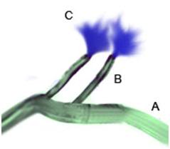 Figure 55: The OroChill nasal cannula may be used if the patient’s jaw is in rigor, or it is otherwise impossible to place the oral catheter. Flows are considerably lower through the nasal cannula and a significant amount of back flow may occur from the nares. For these reasons, the use of the pharyngeal catheter is preferred, when possible.
Monitoring Temperature Descent
As is hopefully clear from much ofthe foregoing discussion, it is critical that cooling data be obtained from every patient where it is possible to do so, as soon as it it possible to do so. Not only is documenting the patient’s temperature descent an important element of care, it also serves as a surrogate marker for the quality of that care, as well as providing valuable scientific data to allow for improvements to the care of future patients. Thus, it is essential that temperature probes be placed, and data acquisition be started as soon as possible after stabilization begins. Where possible, the patient’s agonal temperatures should be recorded at 15 minute intervals up until the time of pronouncement, using whatever method the attending medical staff are using, or are comfortable with being used.

Figure 56: Two examples of remote sensing thermometers that can be used to monitor patient cool down. The device on the left is a non-recording thermocouple thermometer from which temperature measurements must be recorded by hand. It is shown connected to a probe attached to a gastric medication and esophageal (intrathoracic) pressure monitoring balloon. The gastric tube TC probe may be used in cases where an endotracheal tube is in place or will be used.
The DEGTA and the Darwin Rectal Tube (DRT) are both outfitted with copper (CU++)/Constantan (C+) thermocouples (TCs) so that as soon as they are placed, temperature monitoring and data acquisition may be initiated.This is best accomplished by either pre-connecting the TC probes to an automatic datalogging thermocouple thermometer, such as the Digi-Sense DualLogger, or to the data acquisition laptop computer which is collecting other data from the patient’s stabilization and transport. Detailed instructions for the use of the DualLogger, including how to interface it with its waterproof perspex case, are present as Appendix 2 (NOTE: Not included in this article). If the DualLogger is used, it must be not be water proofed in an expedient way, such as by placing it in Ziploc bags, because this still leaves the data entry/setting keys susceptible to being accidentally depressed. This has proved a major source of data loss in the past; the device must be placed in a waterproof hard case to protect the keys from accidentally being depressed while the patient is being moved or air shipped.

Figure 57: Bilateral tympanic temperature monitoring device.
If the patient has an endotracheal tubbe (ET) or will be intubated, tympanic temperature probes may be placed using a device such as one shown in Figure 57. This earphone-like assembly contains two wells of a fast setting silicone sealant which is injected into the ear canal using syringes that are pre-attached to each probe holder (not shown). Once the TC probes have been advanced into the auditory canal to abut the eardrum, the sealant is injected to prevent the ingress of cold water from the HIP, and to secure the probes against accidental dis-lodgement. These, and all other probes, should be left in place at the conclusion of Transport. If such a device is not available, a soft, flexible vinyl TC probe may be advanced into the auditory canal until it abuts the eardrum, where it may be sealed in place using silione swimmer’s ear canal sealing putty, as shown in Figure 58, below.
 Figure 58: Silicone swimmer’s ear sealing putting may be used to seal and secure TC probes into the auditory canal. If this method is to be used, it is important to clean the external auditory meatus with alcohol swabs to remove waxy secretions which may prevent the putty from adhering well and creatina good seal. The probe line should be looped over the top of top of the pinna (after it is secured in the ear canal ) and taped firmly in place to prevent it from accidentally become dislodged.
Where automatic logging equipment is available, temperatures should be collected at 5 second intervals, with consideration given to limitations that may present as a result of the available memory in the data collection device. The lowest acceptable rate of temperature data acquisition is intervals of 5 minutes.

Figure 58: Sample data collection sheet for manual collection of temperature data in the field. This sheet also includes columns for the entry of total body washout/perfusion data. Note that there is a space for recording the time post-pronouncement; this allows for immediate feedback as to how how effectively (rapidly) the patient is cooling. The exact anatomical or physical location in the extracorporeal circuit of thetemperature probes must be entered in the shaded boxes.
At the conclusion of stabilization, the temperatures probes should be left in place and the lead wires carefully separated, coiled up, and placed atop the patient’s thorax. Vinyl coated wire twist ties are ideal for both separating and holding the probes in the coiled position.
Only Cu++/C- TC probes since these may, if necessary, be left in position and used for data acquisition throughout cooling to liquid nitrogen temperature. This eliminates the requirement for replacing the probes with different probes for the subzero parts of the operation, and also helps to ensure continuity of data acquisition, since the same probe should be in the same position from the stat to the finish of the patient’s cryopreservation.
References
1. Hillyard Industries I: Vindicator+ Technical Data Sheet #168. In. St. Joseph, MO: Hillyard Industries, Inc; 2010.
2. Greeley W, Kern, FH, Ungerleider, RM. et al.: Cerebral metabolic suppression during hypothermic circulatory arrest in humans. The Annals of Thoracic Surgery 1999, 67(6):1895-1899.
3. Hixon H: The question column: How cold is cold enough? Cryonics 1985, 6(1):19-25.
4. Bellinger DC WD, duPlessis AJ, Rappaport LA, Jonas RA, Wernovsky G, Newburger JW.: Neurodevelopmental status at eight years in children with dextro-transposition of the great arteries: the Boston Circulatory Arrest Trial. J Thorac Cardiovasc Surg 2003, 126(5):1385-1396.
5. Wypij D, Newburger, JW, Rappaport, LA, duPlessis, AJ, Jonas RA, Wernovsky, G, Lin, M, Bellinger, DC.: The effect of duration of deep hypothermic circulatory arrest in infant heart surgery on late neurodevelopment: the Boston Circulatory Arrest Trial. J Thorac Cardiovasc Surg 2003, 126(5):1397-1403.
6. Ungerleider R, Gaynor, JW.: The Boston Circulatory Arrest Study: An analysis. J Thorac Cardiovasc Surg 2004, 127:1256-1261.
7. Lorentzen G: Food preservation by refrigeration, a general introduction. International Journal of Refrigeration 1978, 1(1):9-12.
8. Ross H MV, Escott ML.: 72-hr canine kidney preservation without continuous perfusion. Transplantation 1976, 21(6):498-501.
9. Sung D, Woods, JE.: Forty-Eight-Hour Preservation of the Canine Liver. Ann Surg 1974, 199(4):422-426.
10. Monden M, Fortner, JG.: Twenty-four- and 48-hour canine liver preservation by simple hypothermia with prostacyclin. Ann Surg 1982, 196(1):38-42.
11. Todo S, Hamada, N, Zhu, Y, Zhang, S, Subbotin, V, Nemoto, A, Takeyoshi, I, Starzl, TE.: Lazaroid U-74389G for 48-hour canine liver preservation. Transplantation 1996, 61(2):189-194.
12. Belzer F, Southard, JH.: Principles of solid-organ preservation by cold storage. Transplantation 1988, 45(4):673-676.
13. Michenfelder J, Milde, JH.: The effect of profound levels of hypothermia (below 14 degrees oC) on canine cerebral metabolism. J Cereb Blood Flow Metab 1992, 12(5):877-880.
14. Haneda K, Thomas, R, Sands, MP, Breazeale, DG, Dillard, DH.: Whole body protection during three hours of total circulatory arrest: an experimental study. Cryobiology 1986, 23(6):483-494.
15. Drabek T, Fisk, JA, Dixon, CE, Garman, RH, Stezoski, J, Wisnewski, SR, Wu, X, Tisherman,, SA K, PM.: Prolonged deep hypothermic circulatory arrest in rats can be achieved without cognitive deficits.
. Life Sci 2007, 8(7):543-552.
16. Goldzveig S, Smith, AU.: A simple method for reanimating rats and mice. J Physiol 1956, 132(2):406-413.
17. Benjamin-Cummings T: Chemical Kinetics, Third Edition. Weinheim: Wiley-VCH Verlag GmbH & Co. KGaA; 1997.
18. Irias J, Olmsted, MR.: Pyruvate carboxylase. Reversible inactivation by cold. Pyruvate carboxylase. Biochemistry 1969, 19:91-98.
19. Avery S, Lloyd, D, Harwood, JL.: Temperature-dependent changes in plasma-membrane lipid order and the phagocytotic activity of the amoeba Acanthamoeba castellanii are closely correlated. Biochem J 1995, 312((Pt 3)):811-816.
20. Zakim D, Kavecansky, J, Scarlata, S.: Are membrane enzymes regulated by the viscosity of the membrane environment? . Biochemistry 1992, 31(46):11589-11594.
21. Perry R: Towards a measure of ischemic injury. . Cryonics 1996, 17(2):21.
22. Harris S: Initial cooling in cryonics from body temperature to ice temperature: Physiologic and physics theory, quality control proposals, historical cryonics case analysis examples, lab experimental results, literature review, numerical recipe examples, and practical summaries and recommendations for the future.
. In. Rancho Cucamonga, CA: Critical Care Research; 2003.
23. Kim H, et al.: Amelioration of impaired cerebral metabolism after severe acidotic ischemia by tirilazad post-treatment in dogs. . Stroke 1996, 27:114-121.
24. Iwatsuki N, et al.: Hyperbaric oxygen combined with nicardipine administration accelerates neurologic recovery after cerebral ischemia in a canine model. . Crit Care Med 1994, 22:858-863.
25. Cervantes M, Moralı´, G, Letechipı´a-Vallejo, G.: Melatonin and ischemia reperfusion injury of the brain. J Pineal Res 2008, 45:1-7.
26. Krep H, Bernd W, Bottiger, BW, et al.: Time course of circulatory and metabolic recovery of cat brain after cardiac arrest assessed by perfusion- and diffusion-weighted imaging and MR-spectroscopy. Resuscitation 2003, 58:337-348.
27. DeGraba T, Pettigrew, C.: Why do neroprotectivedrugs work in animals but not in humans? Neurologic Clinics 2000, 18:475-493.
28. Ginsberg M: Adventures in the Pathophysiology of Brain Ischemia: Penumbra, Gene Expression, Neuroprotection. The 2002 Thomas Willis Lecture. Stroke 2003, 34:214-223.
29. Cheng J, Al-Khoury, L, Zivin, JA.: Neuroprotection for Ischemic Stroke: Two Decades of Success and Failure. NeuroRX 2004, 1:36-45.
30. Roine RO, Kaste M, Kinnunen A, Nikki P, Sarna S, Kajaste S: Nimodipine after resuscitation from out-of-hospital ventricular fibrillation. A placebo-controlled, double-blind, randomized trial. JAMA 1990, 264(24):3171-3177.
31. Longstreth WT, Jr., Fahrenbruch CE, Olsufka M, Walsh TR, Copass MK, Cobb LA: Randomized clinical trial of magnesium, diazepam, or both after out-of-hospital cardiac arrest. Neurology 2002, 59(4):506-514.
32. Landau WM, Schneider S, Machado C, Longstreth WT, Jr., Fahrenbruch CE, Olsufka M, Walsh TR, Copass MK, Cobb LA: Randomized clinical trial of magnesium, diazepam, or both after out-of-hospital cardiac arrest. Neurology 2003, 60(11):1868-1869.
33. Halstrom A, Rea, TD, et al.: Manual chest compression vs use of an automated chest compression device during resuscitation following out-of-hospital cardiac arrest: a randomized trial. JAMA 2006, 295:2620-2628.
34. Lafuente-Lafuente C, Melero-Bascones, M.: Active chest compression-decompression for cardiopulmonary resuscitation. Cochrane Database Syst Rev 2004, (2):CD002751.
35. Aung K, Htay, T.: Vasopressin for cardiac arrest: a systematic review and meta-analysis. Arch Intern Med 2005, 10:17-24.
36. Callaham M, Madsen, CD, Barton, CW, Saunders, CE, Pointer, J.: A randomized clinical trial of high-dose epinephrine and norepinephrine vs standard-dose epinephrine in prehospital cardiac arrest. JAMA 1992, 268:2667-2672.
37. Rincon F, Mayer, SA.: Therapeutic hypothermia for brain injury after cardiac arrest. . Semin Neurol 2006, 26:387-395.
38. Bernard S, Gray, TW, Buist, MD, et al.: Treatment of comatose survivors of out-of-hospital cardiac arrest with induced hypothermia. N Engl J Med 2002, 346:557-563.
39. Liu L, Yenari MA: Therapeutic hypothermia: neuroprotective mechanisms. Front Biosci 2007, 12:816-825.
40. The-Hypothermia-after-Cardiac-Arrest-Study-Group: Mild therapeutic hypothermia to improve the neurologic outcome after cardiac arrest. N Engl J Med 2002, 346:549-556.
41. Nolan J, Morley, PT, Vanden Hoek, TL, Hickey, RW.: Therapeutic Hypothermia After Cardiac Arrest: An Advisory Statement by the Advanced Life Support Task Force of the International Liaison Committee on Resuscitation. Circulation 2003, 108:118-121.
42. Arrich J: Clinical application of mild therapeutic hypothermia after cardiac arrest. Crit Care Med 2007, 35(4):1041-1047.
43. Sandroni C, Nolan J, Cavallaro F, Antonelli M: In-hospital cardiac arrest: incidence, prognosis and possible measures to improve survival. Intensive Care Med 2007, 33(2):237-245.
44. Safar P: Resuscitation from clinical death: Pathophysiologic limits and therapeutic potentials. Crit Care Med 1988, 16:923-941.
45. Safar P, Xiao F, Radovsky A, Tanigawa K, Ebmeyer U, Bircher N, Alexander H, Stezoski SW: Improved cerebral resuscitation from cardiac arrest in dogs with mild hypothermia plus blood flow promotion. Stroke 1996, 27(1):105-113.
46. Polderman KH: Hypothermia and neurological outcome after cardiac arrest: state of the art. Eur J Anaesthesiol Suppl 2008, 42:23-30.
47. Busto R, Dietrich, WD, Globus, MY, et al.: Small differences in intraischemic brain temperature critically determine the extent of ischemic neuronal injury. J Cereb Blood Flow Metab 1987, 7:729-738.
48. Safar P, Behringer, W. (ed.): Brain resuscitation after cardiac arrest. Philadelphia: WB Saunders; 2001.
49. Shimohata T, Zhao H, Steinberg GK: Epsilon PKC may contribute to the protective effect of hypothermia in a rat focal cerebral ischemia model. Stroke 2007, 38(2):375-380.
50. Zhao H, Steinberg GK, Sapolsky RM: General versus specific actions of mild-moderate hypothermia in attenuating cerebral ischemic damage. J Cereb Blood Flow Metab 2007, 27(12):1879-1894.
51. American-Heart-Association: AHA CPR Guidelines: Part 7.2: Management of Cardiac Arrest. Circulation 2005, 112:IV-58-IV-66.
52. Abella B, Rhee, JW, Huang, KN, et al.: Induced hypothermia is underused after resuscitation from cardiac arrest: A current practice survey. Resuscitation 2005, 64:181-186.
53. Merchant R, Soar, J, Skrifvars, MB, et al.: Therapeutic hypothermia utilization among physicians after resuscitation from cardiac arrest. . Crit Care Med 2006, 34:1935-1940.
54. Kennedy J, Green, RS, Stenstrom, R.: The use of induced hypothermia after cardiac arrest: A survey of Canadian emergency physicians. CJEM 2008, 10:125-130.
55. Suffoletto B, Salcido, DD, Menegazzi, JJ.: Use of prehospital-induced hypothermia after out-of-hospital cardiac arrest: A Survey of the National Association of Emergency Medical Services Physicians. Prehosp Emerg Care 2008, 12:52-56.
56. Alam H: Just do it. Critical care medicine, 2008, 36:2456-2457.
57. Skulec R, Kovarnik T, Dostalova G, Kolar J, Linhart A: Induction of mild hypothermia in cardiac arrest survivors presenting with cardiogenic shock syndrome. Acta Anaesthesiol Scand 2008, 52(2):188-194.
58. Hay AW, Swann DG, Bell K, Walsh TS, Cook B: Therapeutic hypothermia in comatose patients after out-of-hospital cardiac arrest. Anaesthesia 2008, 63(1):15-19.
59. Wolfrum S, Pierau C, Radke PW, Schunkert H, Kurowski V: Mild therapeutic hypothermia in patients after out-of-hospital cardiac arrest due to acute ST-segment elevation myocardial infarction undergoing immediate percutaneous coronary intervention. Crit Care Med 2008, 36(6):1780-1786.
60. Bernard S: Therapeutic hypothermia after cardiac arrest: now a standard of care. Crit Care Med 2006, 34(3):923-924.
61. Wolff B, Machill K, Schumacher D, Schulzki I, Werner D: Early achievement of mild therapeutic hypothermia and the neurologic outcome after cardiac arrest. Int J Cardiol 2008.
62. Nagel S, Papadakis M, Hoyte L, Buchan AM: Therapeutic hypothermia in experimental models of focal and global cerebral ischemia and intracerebral hemorrhage. Expert Rev Neurother 2008, 8(8):1255-1268.
63. Nozari A, Safar P, Stezoski SW, Wu X, Kostelnik S, Radovsky A, Tisherman S, Kochanek PM: Critical time window for intra-arrest cooling with cold saline flush in a dog model of cardiopulmonary resuscitation. Circulation 2006, 113(23):2690-2696.
64. Reich H, Angelos M, Safar P, Sterz F, Leonov Y: Cardiac resuscitability with cardiopulmonary bypass after increasing ventricular fibrillation times in dogs. Ann Emerg Med 1990, 19(8):887-890.
65. Angelos M, Safar P, Reich H: A comparison of cardiopulmonary resuscitation with cardiopulmonary bypass after prolonged cardiac arrest in dogs. Reperfusion pressures and neurologic recovery. Resuscitation 1991, 21(2-3):121-135.
66. Radovsky A, Safar P, Sterz F, Leonov Y, Reich H, Kuboyama K: Regional prevalence and distribution of ischemic neurons in dog brains 96 hours after cardiac arrest of 0 to 20 minutes. Stroke 1995, 26(11):2127-2133; discussion 2133-2124.
67. Thoresen M, Wyatt, J. [see comments]: Keeping a cool head, post-hypoxic hypothermia: an old idea revisited. Acta Paediatr 1997, 86:1029-1033.
68. Nozari A, Safar P, Stezoski SW, Wu X, Henchir J, Radovsky A, Hanson K, Klein E, Kochanek PM, Tisherman SA: Mild hypothermia during prolonged cardiopulmonary cerebral resuscitation increases conscious survival in dogs. Crit Care Med 2004, 32(10):2110-2116.
69. Kuboyama K, Safar, P, Radovsky, A, Tisherman, SA, Stezoski, SW, Alexander, H.: Delay in cooling negates the beneficial effect of mild resuscitative cerebral hypothermia after cardiac arrest in dogs: a prospective, randomized study [see comments]. 21 1993, Crit Care Med:1348-1358.
70. Takata K, Takeda, Y, Sato T, Nakatsuka, H, Yokoyama, M, Morita, K.: Effects of hypothermia for a short period on histologic outcome and extracellular glutamate concentration during and after cardiac arrest in rats. . Crit Care Med 2005, 33:1340 -1345.
71. Abella B ZD, Alvarado J, Hamann K, Vanden Hoek T, Becker L.: Intra-arrest cooling improves outcomes in a murine cardiac arrest model. Circulation 2004, 109:2786 -2791.
72. Dietrich W, Busto, R, Alonso, O, et al. 993: Intraischemic but not postischemic brain hypothermia protects chronically following global forebrain ischemia in rats. J Cerebr Blood Flow Metab 1993, 13:541-549.
73. Maier CM, Sun GH, Kunis D, Yenari MA, Steinberg GK: Delayed induction and long-term effects of mild hypothermia in a focal model of transient cerebral ischemia: neurological outcome and infarct size. J Neurosurg 2001, 94(1):90-96.
74. Marion D, Leonov Y, Ginsberg, M, Katz, LM, Kochanek, PM, Lechleuthner, A, Nemoto, EM, Obrist, W, Safar, P, Sterz, F, Tisherman, SA, White, RJ, Xiao, F, Zar, H.: Resuscitative hypothermia. Crit Care Med 1996, 24:S81-89.
75. Zivin J: Editorial comment. Stroke 1999, 30:1899.
76. Wake-County-Government: Wake County Emergency Medical Services. In.: Wake County Government; 2008.
77. Hinchey P, et al.: Out-of-hospital cardiac arrest survival after the sequential implementation of 2005 AHA guidelines for compressions, ventilations, and induced hypothermia. In: SAEM Meeting. vol. Abstract 167. Washington, D.C. ; 2008.
78. Olson J, Hinchey, P, Myers, B.: Wake County EMS Cools Down: System begins induced hypothermia of ROSC patients. In: JEMS. vol. 31: Elsevier Public Safety; 2006.
79. Bayegan K, Janata A, Frossard M, Holzer M, Sterz F, Losert UM, Laggner AN, Behringer W: Rapid non-invasive external cooling to induce mild therapeutic hypothermia in adult human-sized swine. Resuscitation 2008, 76(2):291-298.
80. Kurz A, Sessler, DI, Birnbauer, F, Illievich, U, Spiss, C.: Thermoregulatory vasoconstriction impairs active core cooling. Anesthesiology 1995, 82:870-876.
81. Stolwijk J, Hardy, JD. (ed.): Control of body temperature: Reactions to environmental agents. Bethesda: American Physiological Society; 1977.
82. Doufas A: Consequences of inadvertent perioperative hypothermia. Best Pract Res Clin Anaesthesiol 2003, 17:535-549.
83. Sheffield C, Sessler, DI, Hunt, TK. : Mild hypothermia during isoflurane anesthesia decreases resistance to E. coli dermal infection in guinea pigs. Acta Anaesthesiol Scand 1994, 38:201-205.
84. Lee S, Battistella, FD, Go, K.: Hypothermia induces T-Cell production of immunosuppressive cytokines. J Surg Res 2001 100(4):150-153.
85. Reed R, Bracey, AW, Hudson, JD, Miller, TA, Fisher, RP. : Hypothermia and blood coagulation: dissociation between enzyme activity and clotting factor levels. Circ Shock 1990, 32:141-152.
86. Nirula R, Gentilello, LM. (ed.): Detrimental Effects of Hypothermia New York: Springer US; 2007.
87. Flores-Maldonado A, Medina-Escobedo, CE, Rios-Rodriguez, HM, Fernandez-Dominguez, R. : Mild perioperative hypothermia and the risk of wound infection. Arch Med Res 2001, 32:227-231.
88. Kurz A, Sessler, DI, Lenhardt, R.: Perioperative normothermia to reduce the incidence of surgical wound infection and shorten hospitalization. N Engl J Med 1996, 334:1209-1215.
89. Sheffield C, Sessler, DI, Hopf, HW, Schroeder, M, Moayeri, A, Hunt, TK, West, JM. : Centrally and locally mediated thermoregulatory responses alter subcutaneous oxygen tension. Wouns Rep Reg 1997, 4:339-345.
90. Wenisch C, Narzt, E, Sessler, DI. Parschalk, B, Lenhardt, R, Kurz, A, Graninger, W.: Mild intraoperative hypothermia reduces production of reactive oxygen intermediates by polymorphonuclear leukocytes. Anesth Analg 1996, 82:810-816.
91. Beilin B, Shavit, Y, Razumovsky, J, et al. : Effects of mild perioperative hypothermia on cellular immune responses. Anesthesiology 1998, 89:1133-1140.
92. Jyung R, Mustoe, TA.: Role of cytokines in wound repair. New York: Oxford University Press; 1993.
93. Baigrie R, Lamont, PM, Kwiatkowski, D, Dallman, MG, Morris, PG.: Systemic cytokine response after major surgery. Br J Surg 1992, 79:757-760.
94. Qwarnstrom E, Page, RC, Gillis, S, Dower, SK.: Binding, internalization and intracellular localization of interleukin-1 beta in human diploid fibroblasts. B Biol Chem 1988;, 263::8261-8269.
95. Peterson K, Carson, S, Carney, N.: Hypothermia treatment for traumatic brain injury: a systematic review and meta-analysis. J Neurotrauma 2008, 25(1):62-71.
96. Hammersborga S, Brekkea, KB, Haugena, OM, et al.: Surface cooling versus core cooling: Comparative studies of microvascular fluid- and protein-shifts in a porcine model. Resuscitation 2008, 79:292-300.
97. Merchant R, Abella,BS, Peberdy, MA, Soar, J, et al.: Therapeutic hypothermia after cardiac arrest: Unintentional overcooling is common using ice packs and conventional cooling blankets. Crit Care Med 2006, 34[Suppl.]:S490-S494.
98. Chen R, Chien, S.: Hemodynamic functions and blood viscosity in surface hypothermia. Am J Physiol Lung Cell Mol Physiol 1978, 235:H136-143.
99. Zarins C, Skinner, DB.: Hemodynamics and blood flow distribution following prolonged circulation at 5 degrees C. Am J Physiol 1975, 229:275-278.
100. Hammersborga S, Farstad, M, Haugen, O, Kvalheim, VL, Onarheim, H, Husby, P.: Time course variations of haemodynamics, plasma volume and microvascular fluid exchange following surface cooling: an experimental approach to accidental hypothermia. Resuscitation 2005, 65:211-219.
101. Lewis T: Swelling of the human limbs in response to immersion in cold water. Clin Sci 1939, 4.
102. Farry P, Prentice, NG, Hunter, AC, Wakelin, CA.: Ice treatment of injured ligament: an experimental model. N Z Med J 1980, 91:12-14.
103. Matthew C, Sils, IV, Bastille, AM.: Tissue-specific extravasation of albumin-bound Evans blue in hypothermic and rewarmed rats. Can J Physiol Pharmacol 2002, 80(3):233-243.
104. Kruuv J, Glofcheski, D, Cheng, KH, Campbell, SD, Al-Qysi, HMA, Nolan, WT, Lepock, JR: Factors influencing survival and growth of mammalian cells exposed to hypothermia. I. Effects of temperature and membrane lipid perturbers. J Cell Physiol 1983, 115:179-185.
105. Rule G, Frim, J, Thompson, JE, Lepock, JR, Kruuv, J. : Theeffect of membrane lipid perturbers on survival of mammalian cells to cold. Cryobiology 1978, 15:408-414.
106. Marsh D, Lindell, SL, Fox, LE, Belzer, FO, Southard, JH. : Hypothermic preservation of hepatocytes. I. Role of cell swelling. Cryobiology 1989, 26:524-534.
107. McAnulty J, Ametani, MS, Southard, JH, Belzer, FO.: Effect of hypothermia on intracellular Ca21 in rabbit renal tubules suspended in UW-gluconate preservation solution. . Cryobiology 1996, 33:196-204.
108. Breton S, Brown, D.: Cold-induced microtubule disruption and relocalization of membrane proteins in kidney epithelial cells. J Am Soc Nephrol 1998, 9:155-166.
109. Stefanovich PE, RM, Sheehan, SJ, Tompkins, RG, Yarmush, ML.: Effects of hypothermia on the function, membrane integrity, and cytoskeletal structure of hepatocytes. Cryobiology 1995, 23:389-403.
110. Zieger M, Glofcheski, DJ, Lepock, JR, Kruuv, J. : Factors influencing survival of mammalian cells exposed to hypothermia IV. Effects of iron chelation. . Cryobiology 1990, 27:452-464.
111. Rauen R, DeGroot, H.: Cold induced release of reactive oxygen species asa decisive mediator of hypotherrmiainjury to cultured liver cells. Free Rad Biol & Med 1998, 24(7/8):1316-1323.
112. Hochachka P: Defense strategies against hypoxia and hypothermia. Science 1986, 231:234-241.
113. Endrich B, Hammersen F, Messmer, K.: Microvascular ultrastructure in non-freezing cold injury. Res Exp Med 1990, 190:365-379.
114. Verrey F, Groscurth, P, Bolliger, UI.: Cytoskeletal disruption in A6 kidney cells: Impact on endo-exocytosis and NaCI transport regulation by antidiuretic hormone. J Membr Bio 1995, 145:193-204.
115. Hall S, Komai, H, Reader, J, Haworth, SG. : Donor lung preservation: Effect of cold preservation fluids on cultured pulmonary endothelial cells. . Am J Physiol Lung Cell Mol Physiol 1994, 267: L508-L505 I 507.
116. Breton S, Brown, D.: Cold-induced microtubule disruption and relocalization of membrane proteins in
kidney epithelial cells. J Am Soc Nephrol 1998, 9:155-166.
117. Reed C, Clark, D, editors (ed.): Heat exchangers and hypothermia. Houston TX: Texas Medical Press, Inc.; 1975.
118. Furuse M, Ohta, T, Ikenaga, T, et al.: Effects of intravascular perfusion of cooled crystalloid solution on cold-induced brain injury using an extracorporeal cooling-filtration system. Acta Neurochir 2003, 145:983-993.
119. Behringer W, Safar P, Wu X, Nozari A, Abdullah A, Stezoski SW, Tisherman SA: Veno-venous extracorporeal blood shunt cooling to induce mild hypothermia in dog experiments and review of cooling methods. Resuscitation 2002, 54(1):89-98.
120. Overlie P: Emergency Use of Cardiopulmonary Bypass. Journal of Interventional Cardiology 1995, 8:239-247.
121. Kurusz M, Zwischenberger, JB.: Percutaneous cardiopulmonary bypass for cardiac emergencies. Perfusion 2002, 17:269-277.
122. Holzer M, Behringer, W, Janata, A, Bayegan, K, Schima, H, Deckert, Z, Losert, U, Laggner, AN, Sterz, F.: Extracorporeal venovenous cooling for induction of mild hypothermia in human-sized swine. Crit Care Med 2005, 33:1346-1350.
123. Bernard S, Buist, M, Monterio, O, Smith, K.: Induced hypothermia using large volume, ice-cold intravenous fluid in comatose survivors of out-of-hospital cardiac arrest: a preliminary report. Resuscitation 2003, 56:9-13
124. Bernard S, Rosalion, A.: Therapeutic hypothermia induced during cardiopulmonary resuscitation using large-volume, ice-cold intravenous fluid. Resuscitation 2008, 76:311 – 313.
125. Kamarainen A, Virkkunen I, Tenhunen J, Yli-Hankala A, Silfvast T: Prehospital induction of therapeutic hypothermia during CPR: a pilot study. Resuscitation 2008, 76(3):360-363.
126. Haslam D, James, WP. : Obesity. Lancet 2005, 366:1197-1209.
127. Feldschuh J, Enson, Y.: Prediction of the normal blood volume. Relation of blood volume to body habitus. Circulation 1977, 56:605 – 612.
128. Plaisier BR: Thoracic lavage in accidental hypothermia with cardiac arrest–report of a case and review of the literature. Resuscitation 2005, 66(1):99-104.
129. Xiao F, Safar P, Alexander H: Peritoneal cooling for mild cerebral hypothermia after cardiac arrest in dogs. Resuscitation 1995, 30(1):51-59.
130. Neuropreservation of Alcor patient A-1068. [http://www.alcor.org/Library/html/casereport8504.html]
131. Cryopreservation Patient Case Report: Arlene Francis Fried, A-1049 [http://www.alcor.org/Library/html/fried.html]
132. Jones T: Cryopreservation case report: the cryopreservation of patient A-2063. Cryonics 2005, 26(1):10-12.
133. Leaf J, Quiafe, A.: Case study of neuropreservation. Cryonics 1981, 2(16):21-28.
134. Leaf J, Darwin, MG, Hixon, HL.: Case report: Two consecutive cryopreservations, a comparative study in experimental suspended animation in humans. Cryonics 1985, 6:13-37.
135. Darwin M, Leaf, JD, Hixon, HL.: Case report: Neuropreservation of Alcor patient A-1068. Cryonics 1986, 7(2-3).
136. Darwin M: Alcor member placed in suspension. Cryonics 1985, 6(4):10-19.
137. Darwin M: The journey begins: Alcor member enters biostasis. Cryonics 1987, 8(8):14-22.
138. Bridge S: The cryonic suspension of Alice Black. Cryonics 1988, 9(11):15-25.
139. Edwards N, et al.: Survival in adults after cardiac arrest due to drowning. Intensive Care Med 1990, 16(5):336-337.
140. Husby P, et al.: Accidental hypothermia with cardiac arrest: complete recovery after prolonged resuscitation and rewarming by extracorporeal circulation. Intensive Care Med 1990, 16(1):69-72.
141. Sekar T, et al.: Survival after prolonged submersion in cold water without neurologic sequelae.Report of two cases. Arch Intern Med 1980, 140(6)):775-779.
142. Martin T: Near drowning and cold water immersion. Ann Emerg Med 1984, 13(4):263-273.
143. Ornato J: The resuscitation of near drowning victims. JAMA 1986, 256:75-77.
144. JB. R: Hypothermia: pathophysiology, clinical settings, and management. Ann Intern Med 1978 89(4):519-527.
145. Conn A, Barker, GA, Edmonds, JF, et al. (ed.): Submersion hypothermia and near drowning. Minneapolis: University of Minnesota Press.; 1983.
146. Bolte R, Black, PG, Bowers, RS, et al.: The use of extracorporeal rewarming in a child submerged for 66 minutes. JAMA 1988, 260(3):377-379.
147. Alexander L: The Treatment of Shock from Prolonged Exposure to Cold, Especially in Water. Item No. 24, File No. XXVI. In. Edited by Subcommittee CIO. Washington, D. C.: United States Congress; 1945 (July): 1-228.
148. Mitscherlich A MF: Doctors of Infamy: The Story of Nazi Medical Crimes. New York: Henry Schuman; 1949.
149. Vogelaere P: Cardiac output variations in supine resting subjects during head-out cold water immersion. . Int J Biometeorol 1995, 39(1):40-45.
150. Giesbrecht G: Inhibition of shivering increases core temperature afterdrop and attenuates rewarming in hypothermic humans. Appl Physiol 1997, 83(5):1630-1634.
151. Bristow G (ed.): Clinical aspects of accidental hypothermia. New York: Elsevier; 1985.
152. Hayward J, et al.: Physiological responses and survival time prediction for humans in ice-water. Aviat Space Environ Med 1984, 55(3):206-211.
153. Griepp R, et al.: Prosthetic replacement of the aortic arch. J Thorac Cardiovasc Surg 1975, 70(6):1051-1063.
154. Hayward J, et al.: Thermal and cardiovascular changes during three methods of resuscitation from mild hypothermia. Resuscitation 1984, 11(1-2):21-33.
155. Toner M, et al.: Effects of body mass and morphology on thermal responses in water. J Appl Physiol 1986, 60(2):521-525.
156. Darwin M: Cryopreservation case report: Arlene Francis Fried, A-1049. In. Scottsdale: Alcor Life Extension Foundation; 2004.
157. Darwin M, Pizer, D.: Alcor outstanding support award nominee, Coordinators column: http://www.alcor.org/cryonics/cryonics8907.txt Cryonics 1989, 10(7):11-14.
158. Borlaug G, Fox, BC, Davis, JP.: Community associated methcillin resistant staphylococcus aureus (CA MRSA). Guidelines for Clinical management and control of transmission. In. Edited by Wisconsin Division of Public Health bdswu, 608-267-7711. Madison; 2005.
159. Fridkin S, Hageman, JC, Morrison, M, et al.: Methicillin resistant Staphylococcus aureus disease in three communities. NEJM 2005, 352:1436-1444.
160. Johnson L, Saravolatz, LD.: Community acquired MRSA: current epidemiology and management issues. Infect Med 2005, 22:16-20.
161. Pichichero M, Casey, JR.: Emergence of a multiresistant serotype 19A pneumococcal strain not included in the 7-valent conjugate vaccine as an otopathogen in children. JAMA 2007, 298:1772-1778.
162. Buscha H, Eichwedeb, F, Födischc, Tacconed, MFS.: Safety and feasibility of nasopharyngeal evaporative cooling in the emergency department setting in survivors of cardiac arrest. Resuscitation 2010, 81:943-949.
163. Castren M, Nordberg, P, Svensson, L., et al.: Intra-arrest transnasal evaporative cooling a randomized, prehospital, multicenter study (PRINCE: Pre-ROSC IntraNasal Cooling Effectiveness). Circulation 2010, 122:729-736.
164. Bollera M, Lampea, JW, Katza, JM, Barbutc, D, Beckera, LB.: Feasibility of intra-arrest hypothermia induction: A novel nasopharyngeal approach achieves preferential brain cooling. Resuscitation 2010, 81:1025-1030.
165. Edwards C, Lowe, KC, Röhlke, W, Geister, U, Reuter, P, Meinert , H.: Effects of a novel perfluorocarbon emulsion on neutrophil chemiluminescence in human whole blood in vitro. . Artif Cells Blood Substit Immobil Biotechnol 1997, 25:255-260.
166. Flaim S: Pharmacokinetics and side effects of perfluorocarbon-based blood substitutes. Artif Cells l 1994, 22:1043-1054.
167. Bucala R, Kawakami, M, Cerami, A.. Cytotoxicity of a perfluorocarbon blood substitute to macrophages in vitro. Science 1983, 27:965-967.
168. Wolfson M, Malone, DJ, Wu, J, Hoffman, J, Rozenberg, A, Shaffer, TH, Barbut D.: Intranasal perfluorochemical spray for preferential brain cooling in sheep. Neurocrit Care 2008, 8:437- 447.
169. Guan J, Barbut, D, Wang, H, Li, Y, Tsai, M, Sun, S, Inderbitzen, B, Weil, MH, Tang, W.: Rapid induction of head cooling by the intranasal route during cardiopulmonary resuscitation improves survival and neurological outcomes. Crit Care Med 2008, 36(suppl):S428 -S433.
170. Leonov Y, et al.: Mild cerebral hypothermia during and after cardiac arrest improves neurologic outcome in dogs. J Cereb Blood Flow Metab 1990, 10(1):57-70.
171. Walpoth B, et al.: Accidental deep hypothermia with cardiopulmonary arrest: extracorporeal blood rewarming in 11 patients. Eur J Cardiothorac Surg 1990, 4(7):390-393.
172. Piepgras A, et al.: Rapid active internal core cooling for induction of moderate hypothermia in head injury by use of an extracorporeal heat exchanger. Neurosurgery 1998, 42(2):311-317; discussion 317-318.
173. Harris S, Darwin, MG, Russell, SR, O’Farrell, JM, Fletcher, M, Wowk, B.: Rapid (0.5 degrees oC/min) minimally invasive induction of hypothermia using cold perfluorochemical lung lavage in dogs. Resuscitation 2001, 50(2):189-204.
174. Gill I, Abreu, SC, Desai, MM, et al.: Laparoscopic ice slush renal hypothermia for partial nephrectomy: the initial experience. J Urol 2003, 170(52-6).
175. Ames C, Ramakrishna, V, Weld, KJ, et al.: Laparoscopic renal parenchymal hypothermia with novel ice-slush deployment mechanism. Urology 2005, 66:33-37.
176. Kasza K: Method and apparatus for producing phase change ice particulate saline slurries. In. Edited by Office USP. United States; 2001.
177. Roberts J, Hedges, JR, Chanmugan, AS, et al. (ed.): Procedures pertaining to hyperthermia.: WB Saunders; 2004.
178. Levitt M, Kane, V, Henderson, J, Dryjskimd, M.: A comparative rewarming trial of gastric versus peritoneal lavage in a hypothermic model. The American Journal of Emergency Medicine
1990, 8(4):285-288.
179. Vella J, Farrell, J, Leavey, S, Magee, C, Carmody, M, Walshe, J.: The rapid reversal of profound hypothermia using peritoneal dialysis.
. Ir J Med Sci 1996 165(2):113-114.
180. Bezinger T, Taylor, GW.: Temperature: Its Measurement and Control in Science and Industry., vol. 111. New York: Rheinhold; 1963.
181. Baccino E, Cattaneo, C, Jouineau, C, Poudoulec, J, Martrille, L.: Cooling rates of the ear and brain in pig heads submerged in water implications for postmortem interval estimation of cadavers found in still water. Am J Forensic Med Pathol 2007, 28:80-85.
Appendix 1
Qualifications to the Q10 Rule
‘Reaction rates double for every 10oC rise in temperature’ – it is almost axiomatic in biology in medicine and it is in the pages of learned articles that the the Q10, the ratio of reaction rate at temperature T to that at T + 10. The doubling is usually offered as a fact of chemical (or biochemical) life; unfortunately, it isn’t true.
As originally promulgated in university texts it was “Reaction rates roughly double or triple…”; but in the rapidly proliferating number of papers in biology and medicine a number of fairly important words were omitted such as ‘roughly’, “double or triple.” A number of other important caveats disappeared as well. In fact, the first hint of trouble comes when the diligent scholar tries to cite the Q10 rule. What is then discovered is that while there are many references to the Q10 rule, there is no proper citation. Even searches for the vant Hoff Q10 rule yield disappointment. There is a reason for this, and that is that no such rigorous citation exists. Further consideration of the Arrhenius equation is now in order.
The Arrhenius Equation
The rate of a chemical reaction is described by an empirically-determined equation of the form
rate = k [A]x [B]y
where k is the rate constant, [A] and [B] are the molar concentrations of the species A and B, and x and y are the orders of reaction with respect to A and to B. There may, of course, be only A, or there may be more than two species involved.
The concentrations do not depend significantly upon temperature; the term that changes with a change in temperature is k. That is why all experiments on reaction rates must be done at constant temperature. The temperature-dependence of k is described by the Arrhenius equation (S Arrhenius, 1889, building on earlier work of J H van’t Hoff (1884)):
ln (k2/k1) = (Ea/R) (1/T1 – 1/T2)
where k1 and k2 are the rate constants at (absolute, i.e. Kelvin) temperatures T1 and T2, Ea is the activation energy for the reaction in J mol-1, and R is the gas constant, 8.314 J K-1 mol-1.
The term that is Q10 is k2/k1, and this is how I shall refer to it from now on.
Two Important Points
What is not usually stated by biologists and physicians using the “Q10 rule” kinetics:
-
- k2/k1 depends on the value of Ea;
- k2/k1 depends on temperature – Q10 is not constant. Increasing the temperature decreases k2/k1 .
A Few Calculations
A value for Ea:
Firstly we shall find the value of Ea that would give a doubling of reaction rate between 0oC and 10oC, i.e. for k2/k1 = 2. Then with this value of Ea we shall see what the effect is on k2/k1 at two different 10oC ranges. Remember that the temperatures in the Arrhenius equation must be in K.
For the calculation of Ea we take k2/k1 = 2, T1 = 273 K, T2 = 283 K, R = 8.314 J K-1 mol-1:
| Arrhenius: | ln (k2/k1) = (Ea/R) (1/T1 – 1/T2) | |
| Therefore: | ln (k2/k1) / (1/T1 – 1/T2) = Ea/R | |
| Substituting the values given: | (8.314 x ln 2) / (1/273 – 1/283) = Ea | |
| thus | (8.314 x 0.693) / (1/273 – 1/283) = Ea |
and it is only arithmetic to show that Ea = 44,500 J mol-1 = 44.5 kJ mol-1.
The effect of increasing the temperature on k2/k1:
If we now use this value of Ea and find the value of k2/k1 at different temperatures for this hypothetical reaction, i.e. evaluate
ln (k2/k1) = (44,500/8.314) (1/T1 – 1/T2)
more arithmetic shows the following:
| T1/K | T2/K | k2/k1 | ||
| 273 | 283 | 2.00 | ||
| 373 | 383 | 1.45 | ||
| 473 | 483 | 1.26 |
Indeed, the value of k2/k1, our old – but now unreliable – friend, Q10, falls as the temperature increases.
Finally, the rate of a reaction seems to be determined by Ea. This is true to a good approximation (unlike Q10); but in fact it is the free energy of activation that is the important factor. However, that’s another mini-dissertation: Ea is pretty good until then.
† The first person in cryonics to consider this problem was the mathematician and cryonicist Art Quaife, who did extensive mathematical modeling of this problem in the late 1970s.
Suggestion: Add niacin to the ice/water bath.
Am J Emerg Med. 1988 May;6(3):316-7.
Rapid hypothermia subsequent to oral nicotinic acid ingestion and immersion in warm (30 degrees C) water.
Hubbard RW, Armstrong LE, Young AJ.
PMID: 3370113